
As you will have hopefully seen I have so far published 2 posts in regards to my project of receiving QO-100 (Es’Hail 2). The First being the Building the MiniTiouner V2 from the BATC. The second being Receiving QO-100. These have both been part of my QO-100 RX & MiniTiouner Project.
Since these posts I have progressed further with the project. Firstly by finishing more of the MiniTiouner Build and also doing some upgrades to the RX setup.
MiniTiouner V2 Update
Updates / Changes Made
As you know know, at the end of the last post when I starting testing (and using) my MiniTiouner it was not yet a finished project.
- The box still needed holes drilling in the end plates for the connectors, power and USB port to go through.
- Add the kit needed to supply LNB voltage, 12v & 18v, to both of the connectors from a single power supply using selector switches.
- A few days after making the last post I saw an article online about fitting an OLED screen to the tuner. This was an upgrade I had to have.
With all these changes / upgrades I wanted to make there was a slight buying spree…
- OLED Screen
- Screen
- Connectors
- 2 pin header
- 4 pin header
- 5 pin header
- bag of Female Terminals to fit header blocks
- Wires
- LNB Voltage
- 3 position switches (on/off/on)
- DC/DC converter
- Final Box modifications
- Hand rotary tool. Eg. Dremel
OLED Screen
Before going to the trouble of making up a wiring harness for the screen I wanted to check that it worked. This is because there is a lot of question about which screens work and which don’t.
I quickly soldered some wires to the pins of the screen which already had female header connectors on the other end and attached these to the appropriate pins.
With the screen working I put together a wiring harness to make it look neat.

Here you can see on the top left is the 5 pin header to connect onto the PCB. In the centre is the power, this will replace J2 so has a loop and a feed for the screen. Finally on the right is the 4 pin header for connecting to the screen.
You will need 4 different coloured wires to make this.

Here you will see I have used
- Red = VCC
- Black = Ground
- Green = SCL
- Yellow = SDA

This is the 5 pin header on the PCB just behind the USB board. You could use a 3 pin header but I thought the 5 pin would look better. If I ever want to use the remaining two pins then I can add to the current connector or switch to a 3 and a 2 pin.

The connector onto the screen just plugs straight on.
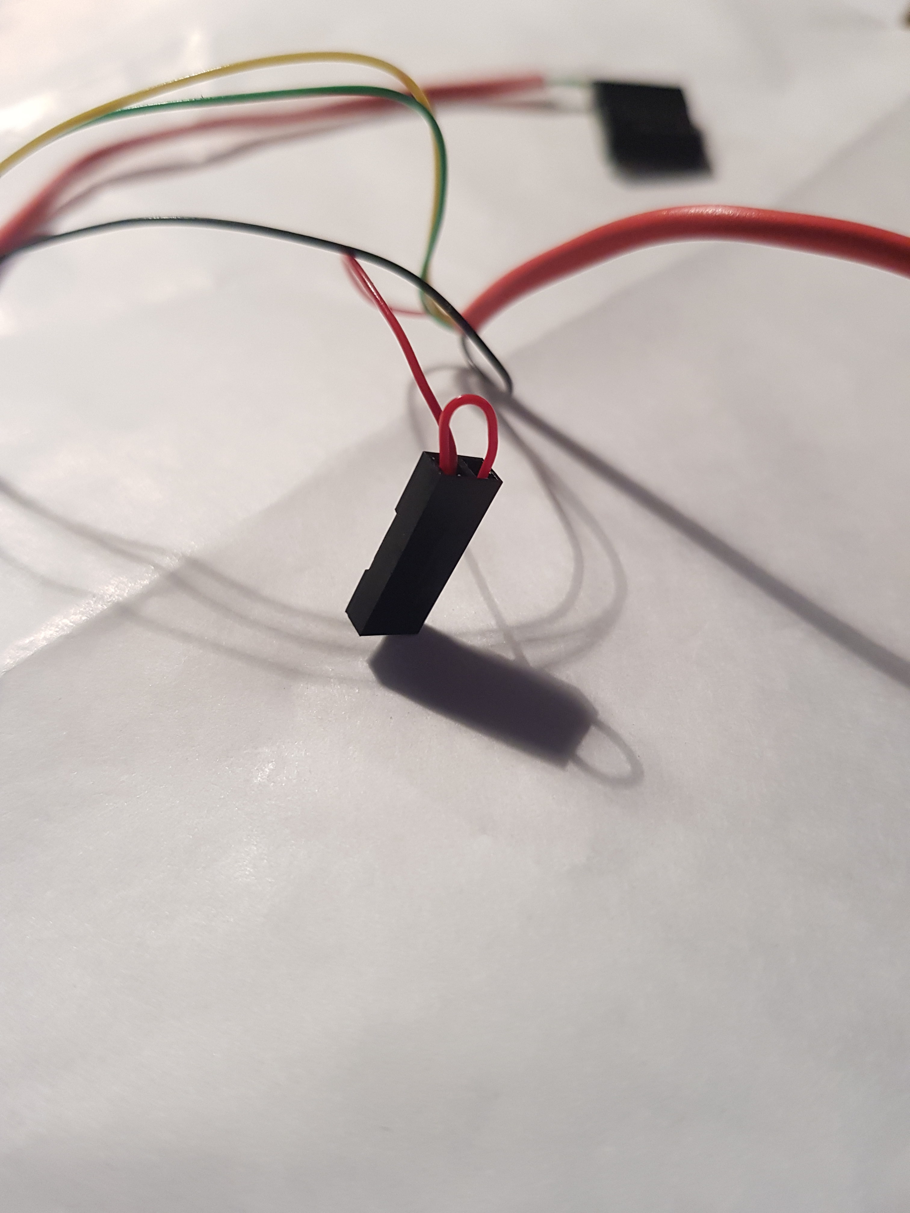
This is the Power connector for the screen. This is to replace the jumper on J2, hence the loop wire, but now will also provide a supply from the DC/DC converter to power the OLED screen.
The next job was to connect it all up and give it a test.

Here you can see the temporary fitment of the screen and Power LED. These will eventually be mounted in the opposite end panel.
Box modifications
The next job was to finally get the holes and slots put in the end panel for the connectors, Power and USB port. I have been intending to get this done for a while as the PCB always slid out with any form of tension on the cables.

To get the correct positions I stuck a piece of paper to the inside of the panel and then put ink on the ends of the connectors. After assembling and then pushing the connectors against the paper. They left a mark which I could use for drilling. Unfortunately the drill did slip a little on the bottom hole but this will be taken up by the locking nut when fitted.
I then did the same with the DC jack and then with the USB port.
They all had to be done separately as they are all at different distances from the panel.
LNB Power / Front Panel Machining
The following day I moved onto installing the LNB power. Due to the parts I have, the whole device will be powered by a 19v supply (or any supply which is appropriate to supply the LNB with Horizontal voltage). The second DC/DC converter will then create a 12v supply from this for the Vertical voltage.
The first task was to create the needed holes in the front panel to hold the switches. At the same time I made the holes for the mains power switch and OLED screen.

Here you can see mid progress. The larges drill I had was only 10mm so the mains switch will be enlarged using the rotary tool. The same with the hole for the screen. I used a smaller drill round all the holes to remove as much material as I could.
The two holes in the middle are for the LNB voltage switches.
Once this was done it was time to work out how to wire it all up. I come up with what looked on paper a simple design but looks a bit messy with having to leave spare cable to be able to remove the board from the box if necessary.

First I installed the switches in the front panel. Followed by the second DC / DC converter board on top of the one that Powers the PCB. I did this using the same method used when installing the first on onto the PCB. I bridged the negative outputs together using a piece of wire.

Mains Power Switch
Next I installed the Mains power switch using spade connectors on the switch. this would allow me to create more space in the box if needed at a later date. The LNB voltages were then wired up to the switches.


It was at this stage I tested the centre output pins for the correct voltages in each position before soldering wires to the output pins and connecting them to the header style pins on the PCB.
Finally a small hole was drilled in the front panel to mount the ‘PCB power’ LED.

With everything now in place the box was reassembled and then tested.


For now the OLED screen is held in position with a piece of blutack. The hole needs to be cleaned up and some black edging material found to put round the edge.
For now the box is complete by some tidying up. With this being done it allowed me to get on with some experimenting with the new dish.
Reception Upgrades
Two upgrades have been done / started.
- Change to a PLL LNB to get a more stable signal.
- Set up a larger dish to improve the received signal.
PLL LNB Upgrade
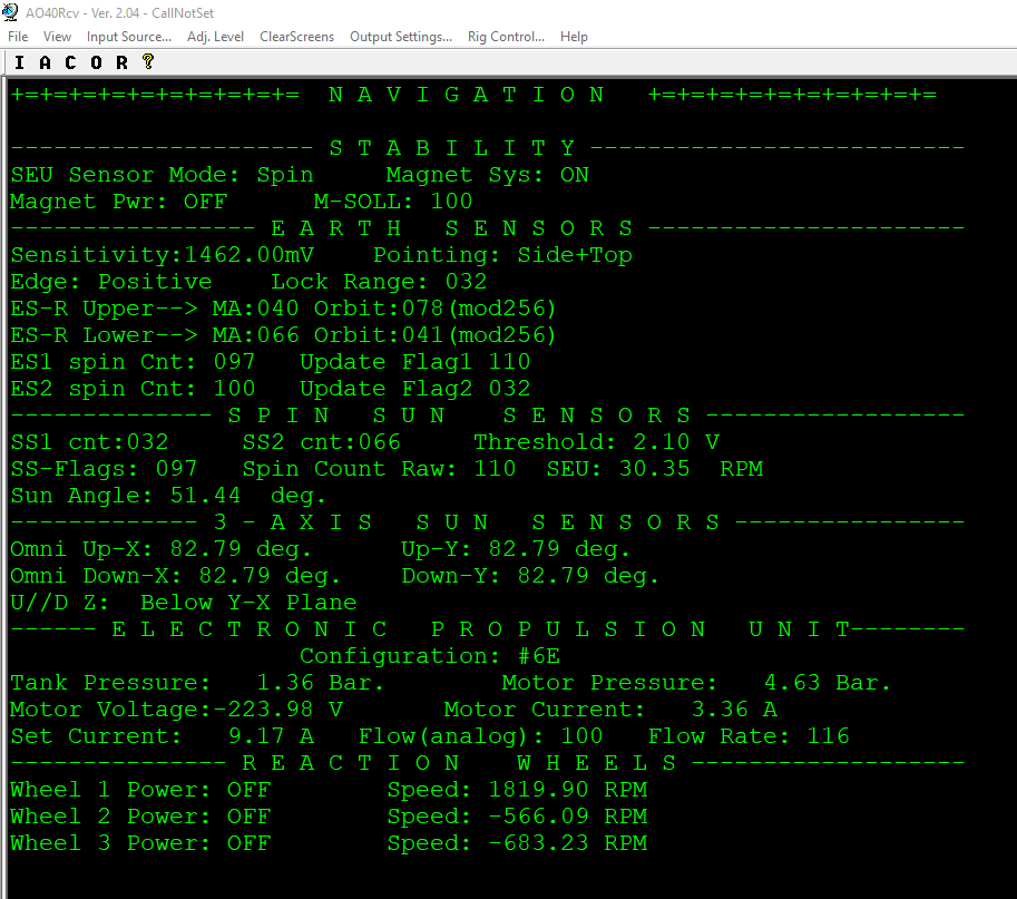
I have upgraded the LNB on my sky dish to one with a PLL instead of a DRO.

This allowed me to better listen to the narrow band transponder meaning not only is the SSB voice clear but also I can now decode data signals including the data beacon.

I was not able to do this previously due to the unstable signal.


New dish testing
The second task, made a lot easier due to completing the Minitiouner v2 receiver with the added LNB Voltage, was the testing of a new dish I was given.

This temporary setup worked well allowing me to receive the beacon on the wide band transponder. Unfortunately the signal was only marginally better then the current sky dish. I may swop these out to have the bigger dish on the wall but ultimately I feel I need to source a 1m plus sized dish.
MiniTioune Stream
I am currently working on a method to stream my MiniTioune output to this website. In the mean time you can view the output of my MiniTioune on the vivaDATV.org website.
09/07/2020 at 1:02 pm
Finds your site helpful and informative
Today I first launched MiniTioner
The order of installing the software as instructed by you has been very helpful
Thanks !!
Yoram
15/01/2024 at 9:36 pm
Hello
I have built the minitiuoner a few days ago and it is not working and I also bought the ELAD tuner and this not working also as I don’t know which software to use…do you have any information please.
Many thanks
Joe 9H1GT
16/01/2024 at 3:38 pm
The Software for the Mini is available here http://www.vivadatv.org/viewforum.php?f=60. You have to register. Or you can also use the Ryde Receiver from the BATC https://wiki.batc.org.uk/Ryde_Receiver. I have no knowledge of the ELAD tuner but by the looks of it will need software designed specifically for it as it is not compatible with the Ryde or MiniTioune. There is also https://wiki.batc.org.uk/OpenTuner Open Tuner which is relatively new which I have not tested myself.